
Why Electrodes Matter: ECG Artifacts
The electrode is a fundamental part of the electrocardiogram (ECG) system. It is the interface between the body and the measuring equipment that allows us to measure and record the ECG.
When recording the ECG, we experience artifacts that can be caused by mains noise, motion and potentials from other muscles. These sources of artifact can distort or attenuate the ECG and result in an increased number of false-positive alarms from automated ECG interpretation systems [1].
Typically, artifacts are removed using hardware and software filters. However, when filtering to remove artifact we can inevitably lose important parts of the ECG. In some cases, aggressive digital filtering has even been shown to remove P-wave entirely [1]. It would therefore be highly desirable to reduce artifacts as much as possible at the very source of the problem, the electrode interface.
In this three-part blog series, we will provide an overview of the key components of ECG electrode optimisation. More specifically, we will describe the key areas of consideration when choosing an appropriate electrode material which are:
(1) the sources of artifact
(2) the electrode-electrolyte interface, and
(3) the electrode-skin interface.
The ECG Signal
The electrocardiogram (ECG) is the biopotential of the heart, recorded using electrodes placed on the surface of the skin. The typical morphology of the ECG comprises of the PQRST waveform, as shown below.

Each of these waves represents a different phase of the heartbeat. The P-wave corresponds to the electrical depolarisation of the atria. The QRS wave corresponds to the ventricular depolarisation. The amplitude of the R wave is typically larger than the P-wave due to the larger muscular mass of the ventricle in comparison to the atria. And finally, the T-wave represents the repolarisation of the ventricles. The repolarisation of the atria is usually not visible in the ECG as it is obscured by the larger R wave.
ECG Artifacts
A change in amplitude, frequency or morphology of the ECG can highlight significant cardiac abnormalities. For the clinician to detect these changes it is important for the signal to be of high quality. Signal distortion, signal attenuation and interference are commonly a result of mains noise, electrode motion and potentials from other muscle groups (EMG). Below, you can see the relative power of each of these artifacts in comparison to the ECG.
![Relative power spectra of QRS complex, P and T waves, muscle noise and motion artifacts based on an average of 150 beats. [2: p.237]](https://images.squarespace-cdn.com/content/v1/5e34309b64f9aa0a9015fa3b/1597756477307-0CRFP9H9DCMAK6UZE69M/frequency%2Bgraph%2Bnew.jpg)
Relative power spectra of QRS complex, P and T waves, muscle noise and motion artifacts based on an average of 150 beats. [2: p.237]
The frequency range of the various artifacts are similar to that of the ECG. If artifacts are present, these will cause interference altering the shape of the ECG. These artifacts and the effect they have on the ECG are discussed below.
All ECG tracing images were created using the MIT-BIH Arrhythmia and noise stress test database [3].
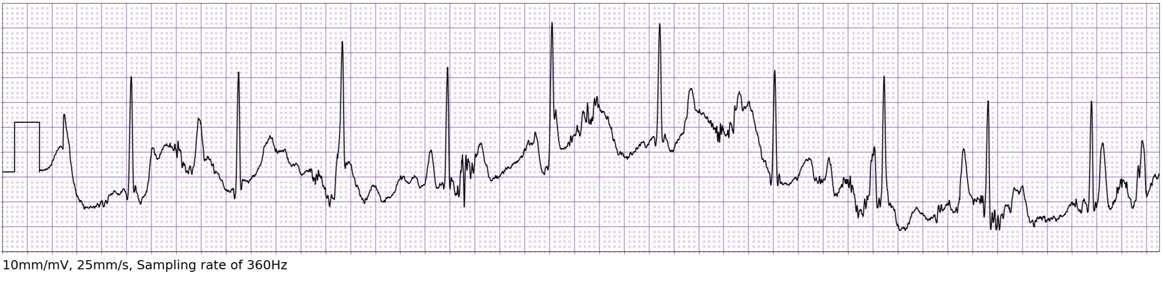
Baseline Wander
Baseline wander (also known as baseline drift) is a low frequency artifact on the ECG. It is typically caused by a variation in electrode contact impedance between two recording electrodes.

Lenis et al. [4] carried out a study comparing various methods to filter out the baseline wander. It was concluded that no current method of filtering was capable of reconstructing the original ECG without modifying the ST segment. ST segment analysis is an important marker for the diagnosis of myocardial infarction [5].
Although it is impossible to remove baseline wander completely, particularly during ambulation, a stable electrode skin-interface can reduce the amount of baseline wander present on the ECG [6].
Mains Noise
Mains noise is a common problem found when recording an ECG. Main noise interference occurs at a frequency of 50Hz (EU) or 60HZ (US), depending on where it is recorded.

The frequency range of an ECG varies depending on its application. According to the American Heart Association [7] the frequency range for ambulatory ECG should be limited to 0.5Hz to 40Hz. However, to provide diagnostic quality resting ECG analysis, a frequency range of 0.05-150Hz is required. The advantage of the larger frequency range is better reproduction of the PQRST waveform, however this does result in increased mains noise interference and baseline wander.
To combat ECG artifact resulting from mains noise, common-mode rejection is usually implemented and aims to remove all of the signal components common to both electrodes, known as the common mode interference. The common mode interference is an unwanted signal that is common to all electrodes compared to ground, highly dominated by interference from the power mains.
Ideally, if we had equal impedance across all electrodes, the mains noise would be removed completely by common-mode rejection. However, due to the small impedance differences across the electrodes, common-mode interference can corrupt the ECG.
Right leg drive is used to further reduce the common-mode interference. The right leg drive system cancels out common-mode interference by using a negative feedback loop. The feedback loop uses a small current opposite to that of the common-mode interference and drives it into the right leg electrode to cancel out the common-mode interference [8].
Motion Artifact
Motion artifact is caused by excessive motion of the patient, creating mechanical deformation at the electrode site by stretching of the skin. As the skin stretches the thickness of the outer layer temporarily decreases. This creates a fluctuation of impedance at the electrode site causing deformation of the ECG.
Excessive motion can also produce an unstable contact between the skin and electrode which will produce an unreadable ECG. Although these problems are inevitable, a choice of high quality materials combined with adequate skin preparation can reduce the effect these have on the ECG.
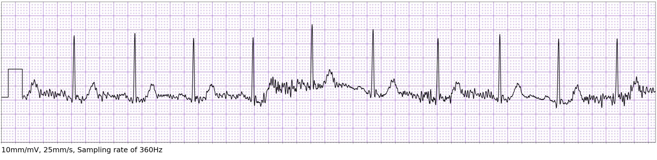
Muscle Interference
Another artifact often seen is Muscle Interference. When other muscles in the body contract, these also exhibit potentials with a similar frequency to that of an ECG. These potentials can interfere with the ECG produced due to an overlap in frequency content.
As the ECG and EMG (electrical activity of the muscles) fall within a similar frequency range, it is these muscle potentials that typically cause a significant amount of in band noise and interference on the ECG.
Motion artifacts and muscle interference are usually quite obvious to spot on the ECG by human interpreters; however, they can trick computer-based interpretation algorithms, leading to false positives and false negatives [1].
Noise is a common problem when recording the ECG. In this blog we reviewed the sources of noise that can occur when recording an ECG and describe measures which have been taken by ECG device manufacturers to reduce noise. However, it is important to remember that noise on the ECG can be significantly reduced by the appropriate choice of electrode materials, particularly for dry electrode systems.
We will cover this in more depth in parts (2) the electrode-electrolyte interface, and (3) the electrode-skin interface. This will provide a detailed overview of appropriate electrode materials and characterisation techniques to enable high quality ECG acquisition.
Sources
[1] Drew BJ, Harris P, Zègre-Hemsey JK, Mammone T, Schindler D, Salas-Boni R, et al. Insights into the Problem of Alarm Fatigue with Physiologic Monitor Devices: A Comprehensive Observational Study of Consecutive Intensive Care Unit Patients. Tereshchenko LG, editor. PLoS ONE. 2014 Oct 22;9(10):e110274.
[2] Tompkins WJ. Biomedical Digital Signal Processing: C Language Examples and Laboratory Experiments for the IBM PC [Internet]. 1983. Available from: https://www.semanticscholar.org/paper/Biomedical-Digital-Signal-Processing%3A-C-Language-PC-Tompkins/39351b188aa0195993d2d753841af8b078d8de47
[3] All ECG tracings created using the MIT-BIH Noise Stress Test Database: Moody GB, Muldrow WE, Mark RG. A noise stress test for arrhythmia detectors. Computers in Cardiology 1984; 11:381-384.
Sourced from Physionet: Goldberger, A., Amaral, L., Glass, L., Hausdorff, J., Ivanov, P. C., Mark, R., ... & Stanley, H. E. (2000). PhysioBank, PhysioToolkit, and PhysioNet: Components of a new research resource for complex physiologic signals. Circulation [Online]. 101 (23), pp. e215–e220.
[4] Lenis G, Pilia N, Loewe A, Schulze WHW, Dössel O. Comparison of Baseline Wander Removal Techniques considering the Preservation of ST Changes in the Ischemic ECG: A Simulation Study [Internet]. Computational and Mathematical Methods in Medicine. 2017 [cited 2020 Aug 18]. Available from: https://www.hindawi.com/journals/cmmm/2017/9295029/.
[5] Macfarlane PW, Browne D, Devine B, Clark E, Miller E, Seyal J, et al. Modification of ACC/ESC criteria for acute myocardial infarction. Journal of Electrocardiology [Internet]. 2004;37 Suppl:98–103. Available from: https://pubmed.ncbi.nlm.nih.gov/15534817/
[6] McAdams E, Webster JG. Medical Devices and Instrumentation / Bioelectrodes [Internet]. 2nd ed. New York: Wiley-Interscience; 1988. Available from: https://onlinelibrary.wiley.com/doi/abs/10.1002/0471732877.emd013
[7] Kligfield P, Gettes LS, Bailey JJ, Childers R, Deal BJ, Hancock EW, et al. Recommendations for the Standardization and Interpretation of the Electrocardiogram. Circulation. 2007 Mar 13;115(10):1306–24.
[8] Gregg RE, Zhou SH, Lindauer JM, Helfenbein ED, Giuliano KK. What is inside the electrocardiograph? Journal of Electrocardiology [Internet]. 2008 Jan ;41(1):8–14. Available from: https://www.sciencedirect.com/science/article/abs/pii/S0022073607007923